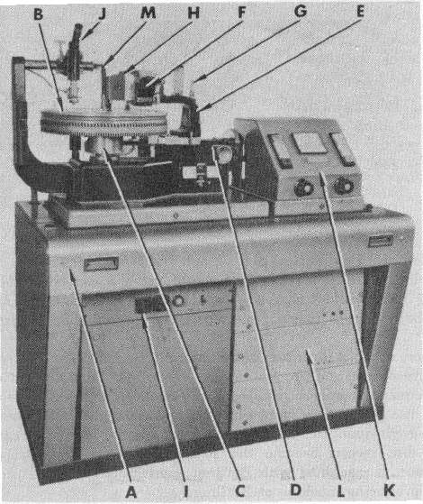
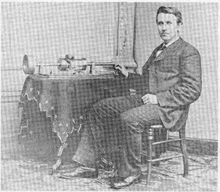
Fig. 13-2A. Neumann master disc recording lathe Model AM-32b with automatic pitch and depth control. (Courtesy, Gotham Audio Corp.)
Emil Berliner, with his invention of the laterally recorded flat disc record, sacrificed the feature of constant groove-velocity recording; thus, tangent error and a loss of high-frequency response resulted as the smaller diameters were approached. However, the disc record was more practical and economical and could be easily reproduced in great quantities by stamping from a metal master. Because of these features, the disc record became the standard for the phonograph industry. Eldridge Johnson, a machinist with Berliner, contributed many improvements to the original reproducing machine of Berliner.
Since the introduction of electrical recording in 1927, the search has been endless for a better recording media, mechanical drives, speed stability, less tangent error, recording heads, pickups, reproducing machines, and materials for pressing the final disc.
Although Blumlein, in 1931, first proposed the 45/45-degree stereophonic method of recording, it has only been in recent years confirmed as standard by the recording industry.
Stereophonic and microgroove recording demonstrate the mutability of the overall disc record industry, all the way from foil to vinyl. Coarse pitch to microgroove, pickup arms weighing from pounds to grams, and frequency ranges extending beyond audibility are all part of the progress of the industry.
Various types of disc recording and the techniques are discussed in this section, with descriptions of recording lathes and their associated equipment.
13.1 What is an electrical transcription?-A disc recording used in radio broadcasting for the transmission of program material, recorded on 10- or 12-inch discs, using microgroove techniques. Before the advent of microgroove recording, transcriptions were recorded in 16-inch disc records, using either lateral or vertical recording at 96 to 150 lines per inch. Many of the transcriptions heard today are actually magnetic tape.
Directly below the lathe bed is a calibrated scale on which are mounted the starting cams and end-groove stop. Three cams for 7-inch, 10-inch, and 12-inch discs are provided. An adjustable end-groove stop for the three standard RIAA groove diameters cause the cutting head either to lift immediately (with eccentric grooves) or with an adjustable delay to provide for a locked groove. A lead screw engaging lever G is interlocked in such a way that the cutter will lift at any time it is not being driven by the lead screw, with a braking assembly to prevent the lead screw from coasting when the end is reached. A vacuum system provides a means of holding down blank discs from 10- to 17-1/4 inches in diameter on the turntable, with a disabling valve to shut off the vacuum holes when they are not in use.
Cutting-head connections are brought to the rectangular box H on the transport sled E by means of a plug to permit the exchange of cutting heads without disturbing the alignment. The connector plugs (for stereo) consist of 6 pins which carry the audio signal, feedback loop, and dc for the stylus heating coil. A release solenoid lifts the cutting head whenever the stop button I is depressed, when the sled hits the end groove-stop, or when the lead screw is disengaged. A dash pot on the front of the cutting-head suspension mechanism is equipped with a perforated piston, with an adjustable shield over the perforations, to allow a wide latitude of adjustment. A tilting mechanism is connected to a moving-coil system which, together with the depth-of-cut control, provides electronic-depth variation, thus eliminating the advance ball generally used.
The turntable motor is of the synchronous type. The motor consists of a gearlike armature about 10 inches in diameter, rotating inside a similar inside gear. By means of a winding, a rotating magnetic field is set up, causing the armature to rotate. The wow and flutter of this particular machine is 0.035 total rms.
For automatic pitch control, three control amplifiers are necessary, and are mounted in the lower portion of the cabinet. A preview head is mounted on the magnetic-tape playback transfer machine to provide the control amplifiers with advance knowledge of the modulation to be fed to the cutting head. The output of the control amplifiers associated with the preview head is fed to the control amplifiers. For monophonic recording, the depth of cut is held constant, while the pitch is varied as a function of the preview information. In stereophonic recording, the pitch control is actuated by the sum of the left and right channel signal, while the depth of cut is varied according to the difference signal obtained from a stereophonic preview head. It is the function of the pitch-control amplifier to translate the preview signal through an equalizer into variations of braking current, which in turn are applied to the pitch-control motor to vary its speed and, with it, the lines per inch of recording.
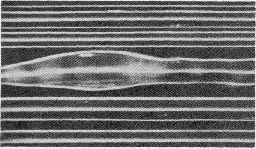
The depth-control amplifier is identical to the pitch-control amplifier; however, its output to the solenoid in the cutting-head suspension produces a varying relief of cutting-head pressure, acting against a counterbalancing spring on the cutting-head mounting mechanism. A microphotograph of a group of recorded grooves, showing the action of the variable pitch and depth control appears in Fig. 13-2B. In the recording of both lateral and vertical modulation (stereo), increased depth requires increased pitch, so any deepening of the groove caused by the depth-control amplifier must be translated into increased pitch. This is accomplished by an integrated amplifier which adds to the pitch-control current whenever increased depth is required. It is claimed that such a system, when properly adjusted, can add up to 6 minutes of recording time on a 12-inch record.
The microscope is 156 power with concentric illumination, brightly lighting the groove and leaving the land between the grooves dark, and is moved across the turntable by means of a rack and pinion gear. The microscope support arm also acts as the vacuum conductor for the vacuum-chuck turntable. The microscope graticule is calibrated to read in 0.001-inch graduations. The chip collector is contained in the lower portion of the cabinet. A pickup arm is generally mounted at the left for playback purposes, and may be used for simultaneous monitoring of the playback signal, while also monitoring the signal from the negative-feedback loop to the cutting head. A half-speed converter permits the turntable to be rotated at 16-2/3 rpm, and half-speed for 45 or 78 rpm for experimental work or for cutting frequency discs.
13.3 Define the term lateral recording.- Lateral disc recording was invented in 1888 by Berliner and Johnson for engraving a sound track on a disc record. A stylus mounted in a cutting head (recording head) is actuated by the sound modulations and moves at right angles to the direction of travel of the recording blank. In lateral recording, the dept of cut and groove width are nearly constant. Both monophonic and stereophonic sound may be recorded by this method.
In a modern vertical-recording head, the actuating mechanism is designed to eliminate any lateral motion. Thus, distortion caused by the combination of a lateral and a vertical motion is eliminated. The sound track made by a vertical recording head varies in both depth and width. Because the variation in width of the groove is small, a greater number of lines per inch may be recorded in a given space.
At one time, vertical recording was considered to be superior to lateral recording; however, with the development of microgroove lateral recording, vertical recording is now considered to be obsolete.
In the original Edison cylinder recorder shown, the record revolved at a constant speed; therefore, the machine recorded with a constant-groove velocity. In the present day recorders, the angular velocity of the turntable is constant and the groove velocity decreases as the smaller diameters are approached. (See Question 13.22.)
13.5 What is hill and dale recording?- It is another name for vertical recording.
13.6 What is a long-playing record?- A disc record having a playing time longer than 5 minutes, 10 to 12 inches in diameter and turning at 33-1/3 rpm, recorded with approximately 150 to 300 lines per inch.
13.7 Define a microgroove recording.- A microgroove recording has from 200 to 300 or more lines per inch, with a groove width in the pressing suitable for reproduction, using a stylus having an included angle of 40 to 55 degrees and a tip radius of 0.001 inch.
For stereophonic recording the lines are the same, but the groove width in the pressing must be such that it may be reproduced using a stylus of 45 to 55-degrees with a tip radius of 0.5 to 0.7 mil. Styli dimensions are discussed in Section 15.
13.8 What are the advantages of microgroove recording?- Longer playing time with low surface noise, wider frequency range, lower distortion and greater dynamic range. The weight of the pickup on the record has been reduced from 27 grams for older type recordings to 0.5 to 3 grams. This lower playback weight results in longer life of the record, lower distortion, and better tracking, and removes the pressure from the side walls of the groove. Be cause of the light pressure, it is important that the playback turntable be level; otherwise, the pickup will skate across the record if jarred.
The reproducing stylus for microgroove recordings has a tip radius of 1 mil (or less) and the included angle is 45 degrees. (See Question 15.5.)
13.9 What are standard turntable speeds?- Standard speeds are 33-1/3 and 45 rpm. It is recognized that both 78.26 rpm and 16-inch coarse-pitch transcriptions running at 33-1/3 rpm are still in limited use; however, these two latter speeds are no longer considered standard. A speed of 16-2/3 rpm is also used for special recording purposes, but it also is not considered standard.
13.10 What medium is used for recording disc records?- Originally soft wax was employed, but in the early 1930's this was replaced with the modern acetate disc, which has also undergone several changes in its material composition since its introduction.
13.11 What materials other than acetate are used for recording on disc records?- For purposes where quality of recording is not of prime importance, materials other than acetate are aluminum, paper, and many different types of plastics.
13.12 What is a pregrooved recording blank?- A disc with a prepared groove in which the recording stylus rides. This type of blank was used in early-day home recording equipment to eliminate the costly lead screw and half-nut.
13.13 What is a recording lathe?- It is another name for a disc recording machine. (See Question 13.2.)
13.14 What is a direct-drive disc recorder?- One in which the power is transmitted to the turntable from the motor by means of gears. (See Question 3.71.)

13.16 What is an idler?- A wheel placed in the mechanical transmission system between the driving member and the turntable in a recorder or reproducing machine.
13.17 Does an idler between the motor and the driving puck have any effect on the speed?- No. It only serves as a means of transmitting the power from the driving source to the turntable. The turntable size and the diameter of the driving puck on the motor determine the speed. (See Question 3.71.)
13.18 What is a puck?- A circular piece of metal or fiber used to transmit power from the driving source to the driven member.
13.19 What is linear speed?- A constant velocity in a given direction.
13.20 What is a constant angular velocity device?- A device driven at a constant speed in rpm.
13.21 What is a weight-driven recorder?- Because of the lack of constant speed drives, early recorders were driven by means of a weight mechanism similar to that of a clock. The recorder was set on a tripod about six feet above the floor. Heavy weights, wound up by means of a windlass, supplied the motive power which was controlled by a centrifugal governor.
13.22 What is a constant-groove velocity recorder?- A disc recording machine so designed that as the recording progresses across the surface of the record toward the smaller diameters, the turntable speed is increased. In this manner, the groove velocity is held constant throughout the whole recording and is the same for any given diameter. The steady increase of speed is accomplished by a planetary drive system contacting the underside of the turntable. The design of this machine permits a greater number of lines per inch to be recorded, thereby increasing the playing time. Twenty-seven minutes may be recorded at 300 lines per inch on an 8-inch disc.
The principal drawback to this type recording is that the playback machine must be of the same design as the recorder in order to obtain exactly the same increase of speed as when recorded. Generally, such machines are used with embossing-type recording heads using a constant-amplitude recording characteristic as described in Question 14.5. It has often been stated that the combination of constant-groove velocity recording and constant-amplitude recording is the classical system of recording.
Constant-groove velocity recorders use an embossing-type stylus with a 1-mil tip radius. The groove velocity is generally around 2 inches per second, at 300 lines per inch. This slow velocity is used only for dialogue recording and will give 93 minutes of recording time on an 8-inch disc. For music recording the groove velocity is increased to 10 ips. The frequency range is approximately 80 to 5500-Hz. (See Questions 13.204 to 13.206).

13.24 What is a variable-pitch recorder?- A disc recorder designed in such a manner that the lines per inch may be varied as the recording progresses. When the program material is of low amplitude, the speed of the cutting-head carriage is slowed down, thereby increasing the number of lines cut per inch. For high amplitudes, the carriage is speeded up to reduce the number of lines per inch. In this manner, greater amplitudes may be recorded and a longer recording time secured.
In the early days of motion picture recording when disc records were used, a 10-minute, 16-inch disc was reduced to a 12-inch disc in this manner. This type recording is also called margin recording and many present day high-quality, long-playing records are made using margin recording with a hot stylus, resulting in superior recordings.
13.25 What is a lead screw?- A threaded shaft used to move the cutting-head carriage across the face of the recording blank on a disc or cylindrical recorder. (See Question 13.2.)
13.26 What is cutting rate?- The number of lines per inch the lead screw moves the cutting head carriage across the face of the recording blank. Before the advent of microgroove recording, the lines per inch for coarse-pitch recording were 96, 104, 112, 128, 136 or greater, increasing in multiples of eight lines per inch. For microgroove recording, 200 to 400 lines per inch are used, 265 lines being average.
13.27 How are the lines per inch changed in a recorder?- In nonprofessional recorders, the lines per inch are fixed. In professional equipment, the lead screw is changed or the gears that drive it. In a variable-pitch machine as described in Question 13.24, the lead screw is rotated by a separate motor and the lines per inch are increased or decreased by controlling the speed of the driving motor.
13.28 In what direction are disc recordings recorded?- From the outside in and rotated in a clockwise direction as viewed from the side being reproduced. In the early days of making broadcast transcriptions (before diameter equalization), if the program material consisted of several records, they were recorded to start outside-in on the first record, with the next record recorded inside-out to compensate for the loss of high frequencies at the smaller diameters. This procedure was followed to the last record, and the listener was often unaware of the loss of high frequencies as the program changed to the next record; however, the increase in high-frequency response was quite noticeable as the larger diameters of the second record were approached.
13.29 What does the term coarse-pitch recording mean?- To distinguish recordings using less lines than that used for microgroove recording, they are referred to as coarse-pitch recordings. The lines for coarse-pitch recording vary between 96 and 150 lines, while those of a microgroove recording range from 200 to 300 lines per inch or more the average being about 265 lines. Variable-pitch techniques may be applied to either type recording.
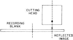
13.30 What is the angle of the recording stylus relative to the surface of the recording disc?- This subject has been under discussion for considerable time and to date no standard has been set for the angle of the recording stylus. The Westrex 3C and 3D cutting heads are operated at an angle of 23 degrees; however, different recording activities may set them to a different angle. Experimental work by Bauer indicates that increasing the angle of the cutting head beyond 23 degrees will reduce the discrepancy between the recorded groove and that of the pressing, and result in a recorded groove of 15 degrees. The principal cause of the discrepancy in the groove is the spring-back of the lacquer, and the recording stylus.
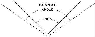
In the normal recording of records the groove walls form an angle of 90 degrees, which is particularly important in recording stereophonic records using the 45/45-degree system. For records cut before the advent of stereo, lateral records were cut using an 87-degree included angle system, on the assumption that after processing the groove grew to 90 degrees. This was controlled in the finished product by the recording engineers, experienced with lacquer-disc recording.
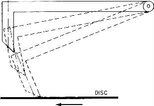
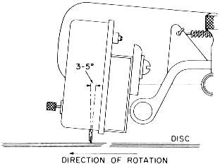
Because of the nature of the stylus suspension in a stereophonic cutting head, the stylus describes an arc in the vertical mode, and because of this motion the cutting face is tilted back from the vertical (Fig. 13-30A). This results in an increase of the included angle of the groove (Fig. 13-30B). In view of this fact, and that the reproducing stylus rides on the wall of the groove and not the bottom, the waveform is distorted and increases with an increase in the recorded level. For the Westrex stereo system, the recording angle is specified to be 23 degrees; however, several activities have studied the angle problem and recommended that the angle of the recording stylus be changed. It is hard to predict the final angle, since factors other than stylus angle inject themselves into the study. Among these factors are: fit of the recording stylus in the recording head, stylus shank material, and the bonding of the jewel in the stylus shank. Any shifting of the jewel tip because of the bonding will cause resonance and also affect the vertical angle. The jewel and stylus shank must act as an integral part.
When reproducing a record cut at a 23-degree angle (or greater), the reproducer stylus angle is set to an angle of 15 degrees to reduce the distortion caused by the difference in the angle of the recorded groove. It has been agreed by the RIAA, NAB, and the manufacturers of sound-reproducing equipment in both the United States and most of Europe that the angle for the reproducing stylus is to be 15 degrees. At the present time, this leaves the record manufacturer with the problem of establishing the correct angle for the recording stylus to produce a 15-degree groove in the finished product. Certain recording activities using coarse-pitch and microgroove techniques still use the 3-degree to 5-degree drag angle, discussed in Question 13-32. (See Questions 16.58 and 16.59.)

13.34 how is flutter measured?- With a flutter bridge as described in Question 22.41.
13.35 What is the standard for wow and flutter in a recorder turntable?- The average deviation measured over a range of 0.5 to 200 Hz, from the mean speed of the turntable while recording, shall not exceed 0.04 percent of the mean speed. The average deviation is measured, using a meter having the same dynamic characteristics of a standard VU meter. The term "average" is defined to mean the average of the measuring device rather than the period of time over which the measurement is made.
The measurement is conducted using a stroboscope disc illuminated by either a 50- or 60-Hz lamp operating from the normal power source. For 33-1/3 rpm, the stroboscope is to have 216 bars or spots in 360 degrees; for 45 rpm, 160 bars or spots are required. For a recorder, not more than 7 bars or spots may pass a given reference point (either direction) in one minute.
13.36 What is the standard for wow and flutter in a reproducer turntable?- The average deviation from the mean speed of the reproducing turntable when reproducing shall not exceed 0.1 percent of the mean speed. The term "average" is defined to mean the average of the measuring device rather than the period of time over which the measurement is made.
The measurement is conducted using a stroboscope disc illuminated by a lamp operated from the normal 50- or 60-Hz power source. For 33-1/3 rpm, the stroboscope disc is to have 216 bars or spots in 360 degrees; and for 45 rpm, 160 bars or spots. For a reproducing turntable, not more than 21 bars are to pass a given reference point in one minute, for either direction.
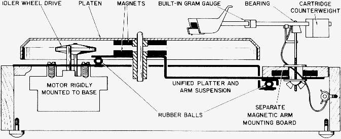
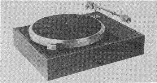
The pickup arm is mounted on a separate structure, isolated by rubber balls, which affords acoustic isolation between the turntable and the pickup arm. The pickup arm is supported on a Single pivot bearing for both vertical and lateral motion. The motor board section supporting the pickup arm is held in place magnetically and aligned with guide pins. This permits easy removal of the arm for experimental work. The arm resonance is below 10 Hz; flutter is less than 0.15 percent; rumble is minus 43 dB below the standard reference of 7 centimeters per second. A view of the complete turntable is shown in Fig. 13-37B.
13.38 What is the effect of flutter on recorded program material?- The music and voices will waver, becoming more noticeable at the higher frequencies. A piano will take on the quality of a harp, Flutter is, in reality, frequency modulation of the program material because of the irregular turntable speed.
13.39 What causes flutter in a disc recorder?- Some of the causes of flutter in a disc recorder are: slippery driving pucks, binding in the drive system, off-center hole in the disc, cutting-head carriage bind on the guide bars, chip brush dragging, and high spots in the drive gears.
13.40 Define the term "once-around."- It is a variation in the sound that occurs once per revolution of the turntable. (See Question 13.33.)
13.41 What causes a pattern of spokes in a disc record?- Vibration in the recorder or excessive alternating current hum in the amplifier. The pattern resembles wheel spokes when observed under a light. During reproduction, patterns cause a low-frequency rumble and high background noise.
13.42 What is a moire pattern?- A shadow pattern on a disc record caused by vibration. It is so named because of its resemblance to moire cloth.
13.43 What is the cause of rumble in a recording?- Rumble is generally a low-frequency sound caused either by the reproducing turntable drive mechanism, or it was recorded in the original master recording. Low-frequency noise and rumble is sometimes induced in the recording lathe by earth noises, drive gears, and the cutting-head carriage rails. (See Question 23.76.)
13.44 How does turntable rumble effect the reproduction of stereophonic records?- Turntable rumble has a pronounced effect since most of the rumble is in the vertical plane. Turntables employed for the reproduction of stereophonic recordings must have a low rumble factor, at least 10, and preferably 20 dB below that of a turntable used to reproduce laterally-cut records.
13.45 What is a drive hole?- An offset hole in a recording blank for setting over a pin in the recorder turntable to prevent slippage.
13.46 What is a recording medium?- Any material used for the purpose of recording a sound track. Common materials are: photographic film, acetate discs, magnetic tape, and plastics.
13.47 What does the term groove velocity mean?- The amount of disc surface passing under the stylus tip in one second. For constant-angular recording, the groove velocity is continually changing with the diameter of the record groove, decreasing as the center or smaller diameters are approached. For constant-groove velocity recording, the groove velocity is the same at any point on the disc, regardless of the diameter. (See Question 13.22.)
| Recording-speed rpm | Recording-blank diameter | Groove velocity inches per second |
| 33-1/3 | 16-inch coarse pitch | 10 to 25 |
| 33-1/3 | 12-inch microgroove | 8.5 to 20 |
| 45 | 7-inch microgroove | 9 to 19 |
| 78.26 | 12-inch coarse pitch | 16 to 48 |
13.48 What are the average groove velocities for different recording speeds?- See Fig. 13-48.
13.49 Describe the effect of a hot and cold stylus on the frequency response of a microgroove recording.- The results from a study by Jackson of this effect are tabulated below. With a reference level of 5 centimeters per second, unfiltered output measurements were taken of the signal frequencies from 30 Hz to 15,000 Hz, using both a hot and cold stylus. The tests were conducted by turning the stylus heater current on and off, and each frequency recorded from an 8-inch diameter to 7.5 inches on the same disc. There was no noticeable difference from 30 Hz to 1000 Hz. The first noticeable change occurred at 2000 Hz, with larger differences occurring as the frequency was increased up to 15,000 hZ. The hot-stylus recording measured an increased output over the cold stylus as tabulated below.
| 2000 Hz + 0.2 dB 4000 Hz + 0.2 dB 6000 Hz + 0.5 dB 8000 Hz + 0.6 dB | 10,000 Hz + 1.3 dB 12,000 Hz + 1.6 dB 15,000 Hz + 2.0 dB |
The tests tabulated were made using a Westrex Corp. 3C stereophonic recording head, a Cappscoop 90-degree prewired stylus, and a Scully recording lathe. The discs were manufactured by the Audiotape Corp.
13.50 What effect does changing the diameter and groove velocity have on a 78.26 rpm record?- Very little, the losses at the smaller diameters are negligible compared to the same frequency at a diameter of 11.5 inches. (See Question 13.49.)
| Diameter | 50,000 Hz | 100,000 Hz |
| 11.5 inch | Same hot and cold | Same hot and cold |
| 8 inch | Same hot and cold | Same hot and cold |
| 6 inch | Same hot and cold | Same hot and cold |
| 4 inch | + 0.2 dB cold | + 0,1 dB cold |
| Diameter | 10,000 Hz | 15,000 Hz |
| 11.5 inch | + 0.2 dB cold | + 0.9 dB hot |
| 8 inch | + 1.0 dB hot | + 1.8 dB hot |
| 6 inch | + 2,5 dB hot | + 2.0 dB hot |
| 4 inch | + 4.7 dB hot | + 2.3 dB cold |
Fig. 13-49. Effects of hot and cold stylus on frequency response.
13.51 What are the diameter losses for 45-rpm Recordings?- See Question 13.49.
13.52 What is the formula for calculating linear velocity?
Velocity = L x f
where,
The final quality of the disc is dependent on the extreme flatness of the aluminum substrate. The manufacturer must be concerned with minute pits or pimples on the aluminum surface, which result in defects of equal degree in the lacquer coating regardless of the thickness. In addition, during the coating process, the temperature and humidity must be closely controlled and the air supply filtered to remove 99 percent of particles of 0.30 microns or larger. The viscosity of the lacquer must be kept within 5 percent of the coating viscosity, and the temperature to within 2 degrees Fahrenheit, with the pressure of the lacquer entering the coating head absolutely constant.
13.54 What is an instantaneous recording?- A recording made on an acetate disc. See Question 13.53.
13.55 Define the term, "coarse-pitch recording."- Recordings made using 96 to 120 lines per inch are termed coarse-pitch, contrasted to microgroove recordings made using 250 to 400 lines per inch. To differentiate between these two recording techniques, dimension and equipment used in the first category are termed coarse-pitch and will be referred to as such throughout this work.
13.56 What is the cosmetic effect in a lacquer disc?- The aluminum used for making recording discs is stretched to obtain as near as flat a surface as possible, which causes a cosmetic effect. Since the lacquer is not completely opaque, certain cosmetic effects on the surface of the aluminum disc manifest themselves by two flashes per second as the disc revolves. To the recordist unaware of this effect, the disc may be rejected as unsuitable for recording. Discs of this nature are quite satisfactory for recording if they meet the other requirements for a good recording disc.
13.57 What are the recommended disc sizes for recording masters?- See Fig. 13-57. At least one unmodulated groove is to be recorded at both the start and end of the recorded area. The diameter of the innermost modulated groove is to be not less than 4-3/4 inches for 33-1/3 rpm discs and not less than 4-1/4 for 45-rpm discs. The center hole must be concentric with the recorded groove spiral within 0.005 inch and has been standardized as follows:
| Nominal | Finished Disc (pressing of instantaneous) | 0uter Modulated Groove Diameter (outside start) |
| 12 inches | 11-7/8 (+-) 1/32 inches | 11-7/16 inches maximum |
| 10 inches | 9-7/8 (+-) 1/32 inches | 9-7/16 inches maximum |
| 7 inches | 6-7/8 (+-) 1/32 inches | 6-9/16 inches maximum |
Fig. 1 3-57. Recommended disc sizes for master recordings.
| 33-1/3 rpm | 0.286 inch + 0.001, - 0.002 inch diameter |
| 45 rpm | 1.504 inches (+-) 0.002-inches diameter |
The warp of the disc, when measured using a surface indicator, is to be not greater than 1/16 inch and within any 45-degree segment not greater than 1/32 inch. Following the innermost recording groove, a leadout spiral and a concentric locking groove are provided.
13.58 What is the cause of surface noise using cold-stylus recording techniques?- The causes of surface noise in cold-stylus recording are many and varied. Among them are dull recording stylus, improper alignment, hard recording blank, and many of the effects noted in Questions 13.65 to 13.68. Surface noise may also be induced in the reproduction because of vertical pressure of the pickup, improper tracking angle, pickup stylus at an improper angle with respect to the disc surface, and pinch effect.
3.59 What causes noisy pressings?- Generally speaking, a pressing can be no quieter than the original recording; however, finger prints on the master and poor compounds used for pressing can cause a considerable amount of surface noise.
13.60 How does the signal to noise vary for hot and cold-stylus recording? Studies made by Jackson show the signal-to-noise ratios for a master disc in Fig. 13-60A. Older type discs will measure between 2 and 4 dB less signal-to-noise ratio.
A disc with a once-around, warp, bump or unevenness produces a swinging-type noise, and the signal-to-noise ratio under these conditions may measure as given in Fig. 3-60B.
The measurements were made using a constant velocity of 5.5 cm/sec at 1000 Hz, using a Westrex 3C recording head, a Cappscoop prewired stylus, Scully recording lathe, and Audiotape Corp. recording disc. The signal-to-noise measurements as given in Figs. 13-60A and B apply to both 45 and 78.26-rpm recording, assuming a hot stylus is used. (See Question 13.49.)
13.61 Is it permissible to play back a master to be processed?- No. Masters are never played back for fear of damaging the sound track. As a rule, two discs are cut simultaneously, a master and a playback for checking quality and cues. The master is checked by visual inspection only.
13.62 How does the hardness of an acetate disc affect the frequency response?- For cold-stylus techniques, the high-frequency response is increased at the expense of background noise. Generally speaking, all discs regardless of manufacture have the same frequency characteristics at the larger diameters. However, this is not true for smaller diameters, as high frequencies fall off at different rates, depending on the degree of hardness.
In addition, the situation is further complicated by the diminishing groove velocity at the smaller diameters. This may be partially compensated for by the use of a diameter equalizer or a hot stylus. (See Questions 13.111 and 13.153.)
| Diameter | 12-inch | 10-inch | 8-inch | 6-inch | 5-inch | 4-inch |
| Hot stylus | -68.5 dB | -69 dB | -69.5 dB | -69.5 dB | -70 dB | -70 dB |
| Cold stylus | -67.0 dB | -66 dB | -63 dB | -60 dB | -57 dB | -53 dB |
Fig. 13-60A. Signal-to-noise ratios for a master disc.
| Diameter | 12-inches | 10-inches | 8-inches | 6-inches | 4-inches |
| Hot stylus | -66/58 dB | -66/58 dB | -66/60 dB | -67 dB | -67 dB |
Fig. 13-60B. Signal-to-noise ratios for a deformed master disc.
13.63 Is there an appreciable difference between recording discs of different manufacture?- There is very little difference among those of good manufacture. Experience indicates the frequency response of a particular disc is the combination of cutting-head frequency response, length of the recording stylus, diameter of the recording area, the electronics of the recording system, and if the recording is made using a cold or hot stylus. Using hot stylus recording techniques, the resistance of the disc to the stylus is practically nonexistent with regard to frequency response. (See Question 13.49.)
13.64 What is white noise?- When the noise spectrum is uniform over a wide frequency band, it is referred to as white noise because it is analogous to white light. (See Question 1.140.)
13.65 What is orange peel?- A term applied to the surface of a recording blank which looks similar to orange peel. Such surfaces have high background noise.
13.66 What is a buzz?- A rasping noise heard in the background of a record and is generally caused by hum or noise in the system.
13.67 What is chatter?- A rattle in the reproduction caused by improper seating of the reproducing stylus in the sound track.
13.68 What is a chip?- The material removed from a record during the recording process.
13.69 What is an unmodulated groove?- A groove cut in a record without modulation. Such grooves are used at the start and ending of a recording and also to measure the signal-to-noise ratio.
13.70 What is an undulation?- A rising or falling appearance of the groove.
13.71 What is a dry cut?- A bad groove in a disc record. The chip is kinky and brittle because of a dull or improperly aligned recording stylus. It may also be caused by recording blanks which have become hardened with age. This effect is noticed when using cold-stylus recording techniques.
13.72 What is a cutover?- A breaking through the wall of one groove into the wall of the next groove. It is caused by overmodulation.
13.73 What causes a stylus to whistle when recording?- the stylus may be dull or out of alignment. Also, the disc may be old and dry. This effect is related to cold-stylus recording.
13.74 What causes a gray cut?- A cold stylus that is dull or a disc that is dry and hard.
13.75 What is the depth of cut?- The distance from the surface of the recording blank to the bottom of the groove. (See Question 13.150.)
13.76 What is a spiral out?- A groove at the inside end of a recording for the purpose of tripping an automatic record changer.
13.77 What is a locked groove?- A spiral groove at the inside end of a recording, closed by a concentric groove, for the purpose of tripping an automatic record reproducing machine. The locked groove provides a groove for the pickup stylus to ride in until the mechanism trips.
13.78 What is twinning?- When two grooves overlap or touch as a result of overmodulation. Twinning is also caused by improper groove-to-land ratios or a defective lead screw. (See Question 13.25.)
13.79 What is land?- The space between adjacent recording grooves.
13.80 What causes an echo effect in a blank groove?- A sound from an adjacent groove caused by overmodulation. Although the groove wall is not damaged, it is deformed by the excessive modulation in the adjacent groove. If the relationship is just right, with respect to the original modulation, what appears to be an echo is heard.
13.81 What is skating?- A condition existing when a reproducing stylus is pinched out of the groove and moves rapidly across the face of the record. Skating is also caused by the reproducing turntable not being level. It is particularly important, for microgroove reproduction, that the turntable be level in all directions.

13.83 What is an advance ball?- A rounded sapphire support mounted on the cutting head, either beside or ahead of the stylus, and bearing on the surface of the record. Its purpose is to maintain a constant depth of cut regardless of irregularities in the surface of the record.
Advance balls were originated for soft-wax recording, before the advent of the acetate disc, and are still used in some instances for acetate-disc recording. However, with the use of automatic depth control and hot-stylus recording, advance balls are not used to the extent they were once used. If the recording disc has been stored for several hours at a temperature of 130-degrees Fahrenheit, it can be scored by the advance ball. In this instance, a hard deposit adheres to the advance ball, and if not removed, will score all succeeding discs. Lacquer discs should not be stored in a temperature exceeding 100-degrees Fahrenheit. (See Question 13.49.)
The placement of the advance ball in relation to the cutting-head stylus is shown in Fig. 14-2I.
13.84 What is the formula for calculating the wave length of a recorded sound wave?
| Wavelength = | V F |
where,
V is the velocity of the record groove in inches per second at a given diameter,
F is the frequency of the recorded wavelength.
13.85 What is the standard signal-to-noise ratio for monophonic record reproduction?- For monophonic record reproduction the low-frequency noise voltage generated by the turntable, pickup, and equalizer, when playing an essentially rumble-free silent groove, shall be at least 40 dB below a reference level of 1.4 centimeters per second peak velocity at 100 Hz. (See Question 23.130.)
The frequency response of the pickup and its equalizers shall conform to the NAB standard reproducing curve, as shown in Fig. 13-95. The amplifier and indicating meter shall have uniform frequency response, within plus-minus 1 dB between 10 and 250 Hz, with the 500-Hz response 3 dB below the 100-Hz response, and an attenuation rate of at least 12 dB per octave at frequencies above 500 Hz (this may be obtained by means of a low-pass filter). The amplifier and indicating meter shall decrease at a rate of at least 6 dB per octave below 10 Hz.
The meter is to have the same dynamic characteristics as a standard VU meter USASI (ASA) C16-1961. (See Question 10.3.) lf the meter fluctuates, the maximum values are used. In making these measurements, the pickup-arm resonance must fall outside the prescribed passband or be sufficiently damped to remove any possibility of affecting the measurement. The results are the electrical measurement, and not the aural annoyance value of low-frequency noise, such as rumble at frequencies below audibility. A strong low-frequency noise such as rumble, can cause severe intermodulation distortion with the low-frequency response of modern sound reproducing systems, The inaudible noise can be more serious than the indicated noise.
High-frequency noise is measured with the same meter characteristics when reproducing on a flat velocity basis, over a frequency range of 500 to 15,000 Hz, and shall be at least 55 dB below the level obtained under the same conditions of reproduction, using 1000 Hz recorded at a peak velocity of 7 centimeters per second. The frequency response at 500 Hz shall be 3 dB below the response at 1000 Hz, and shall fall off at a rate of at least 12 dB per octave below 500 Hz (using a high-pass filter). The response of the system at 15,000 Hz shall be 3 dB below the response at 1000 Hz and shall fall off at a rate of 12 dB per octave above 15,000 Hz.
13.86 What is the standard signal-to-noise ratio for stereophonic record reproduction?- For stereophonic record reproduction, the low-frequency noise voltage in each channel generated by the turntable, pickup, and equalizer when playing an essentially rumble-free silent groove--shall be at least 35 dB below a reference level of 1 centimeter per second peak velocity at 100 Hz in the plane of modulation (vertical or lateral). The frequency response of the pickup and preamplifier shall conform to the NAB standard reproducing curve (Fig. 13-95), and the test equipment as stated in Question 13.85. The reference level of 1 centimeter per second peak velocity at 100 Hz corresponds in amplitude to 5 centimeters per second peak velocity at 500 Hz as it is in the constant-amplitude portion of the recording characteristic.
The high-frequency noise is measured with the same meter characteristics when reproducing on a flat velocity basis, over a frequency range of 500 to 15,000 Hz, and shall be at least 50 dB below the level obtained under the same conditions of reproduction, using 1000 Hz and fall-off rate of at least 12 dB per octave below 500 Hz. The response of the system at 15,000 Hz shall be 3 dB below the response at 1000 Hz and fall off at a rate of at least 12 dB per octave above 15,000 Hz.
13.87 What are the standard recording reference levels used for monophonic and stereophonic recording?- The NAB standard specifies that for monophonic microgroove recording, the recorded program level is to produce a reference level (using a standard VU meter) equivalent to a 1000-Hz tone, recorded at a peak velocity of 7 cm per second.
For stereophonic program material, the reference level is to be equivalent to a 1000-Hz tone, recorded at a peak velocity of 5 cm per second, as indicated on a standard VU meter. This is approximately 3 dB below the level for monophonic recording.
13.88 What percentage distortion is permissible for microgroove recording at 33-1/3 rpm?- The distortion at 400 Hz should not exceed 1 percent total rms harmonic distortion. The intermodulation distortion should not exceed 3 percent using 100 and 7000 Hz mixed in a ratio of 4:1. Intermodulation measurements are discussed in Question 23.113.
13.89 What percentage distortion is permissible for microgroove recording at 45 rpm?- The distortion at 400 Hz should not exceed 1 percent total rms harmonic distortion. The intermodulation distortion using 100 and 7000 Hz should not exceed 4 percent mixed in a ratio of 4 to 1.
13.90 What are the recommended land-to-groove ratios?- For other than microgroove recording the ratio is set by the width of the groove, which is generally less than 4 mils and not greater than 5 mils, with a land-to-groove ratio of 60:40.
For 33-1/3 rpm microgroove recording, the groove width is approximately 2.75 to 3.0 mils, with a groove-to-land width ratio of 70:30. For 45-rpm microgroove recording, it is the same. If variable-pitch recording is used, the groove-to-land ratio is constantly changing.
13.91 What is the appearance of a vertical-recorded groove?- Its appearance is as shown in Fig. 13-91. In vertical recording the depth of the cut and its width are constantly changing with the percentage of modulation. The sound track is engraved in the bottom of the groove. The unmodulated groove width is maintained at 0.003 inch for 125 to 150 lines per inch.
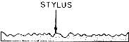
13.92 What is the appearance of a lateral-recorded groove?- It is as shown in Fig, 13-92. The groove depth and width remain almost constant with the grooves moving in a lateral direction or from side to side. The amount of lateral movement is dependent on the percentage of modulation of the audio signal.
13.93 Why was the NAB standard changed from a recording characteristic to a reproducing standard?- In the original Standard (1949 and 1953) only the recording characteristic was specified. However, it was found from experience that it was more practical to supply the manufacturer of record-reproducing equipment a test record with a standard reproducing characteristic than to specify the recording characteristic for the record manufacturer. Therefore, in the NAB Standard, March 1964, only the reproducing characteristic is specified, with the understanding that the record manufacturer will adjust his recording characteristic to an inverse characteristic of the reproducing standard. On this basis, a reproducing standard was specified.

13.94 What is the recording and reproducing characteristic for vertical recording?- Although it is recognized that vertical recording is no longer used, the characteristics for both recording and reproducing are given in Fig. 13-94 for reference. It will be noted that the turnover frequency is 400 Hz.

13.96 What is the standard reference level for monophonic recording?- For monophonic recording the recorded program level shall produce the same deflection on a standard VU meter as that reproduced by a 1000-Hz tone recorded at a peak velocity of 7 centimeters per second. A margin of 10 dB is required between the sine-wave load handling capabilities of a system and the level of the program material measured on a standard VU meter. (See Question 10.3.)
13.97 What is the standard reference level for stereophonic recording?- For stereophonic recording, the reference program level shall, for each channel in its plane of modulation, produce the same reference deflection on a standard VU meter as that produced by a 1000-Hz tone recorded at a peak velocity of 5 centimeters per second. This is approximately 3 dB below the level of the monophonic reference level.
Experience indicates that at least a 10-dB margin is required between the sine-wave load handling capabilities of a system and the level of the program material, measured on a standard VU meter. This would then contemplate program material running as high as a velocity of 21 centimeters per second and is believed to be the maximum velocity that can be traced without excessive distortion at the smaller diameters of a disc turning at 33-1/3 rpm.
13.98 What is a minigroove recording?- A 78.26-rpm recording made using microgroove techniques, including hot-stylus and variable-pitch recording. Although the number of lines per inch is greater than is normally used for 78-rpm recording, it is not enough so that the record may be called long playing, or extended play. The frequency characteristic used is that of Fig. 13-95, known as the RIAA recording characteristic.
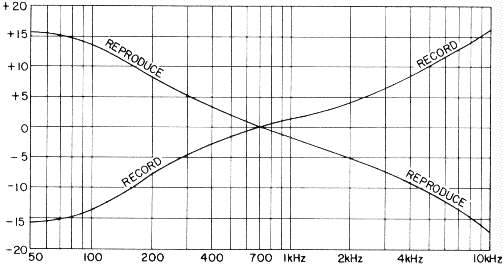
13.99 What is an orthocoustic recording?- It is a recording characteristic introduced by RCA Victor several years ago for recording 16-inch transcriptions at a speed of 331/3 rpm. This characteristic, shown in Fig. 13-99, had been used by the broadcasting and recording industries for many years until the advent of the RIAA recording characteristic.
The orthocoustic characteristic makes use of pre-equalization in the recording circuits and post-equalization in the reproducing circuits as described in Question 6.11. The principal advantage gained by the use of such equalizers is the increased signal-to-noise ratio above 2000 Hz.
13.100 What is an orhophonic recording characteristic?- A reproducing characteristic introduced by RCA Victor some years ago; it is similar to the RIAA characteristic. The orthophonic recording and reproducing characteristic employs both pre- and post-equalization, discussed in Question 6.11.
3.101 Define constant-amplitude recording.- Constant-amplitude recording indicates a mechanical recording characteristic for a fixed amplitude of a sine-wave signal; the resulting recorded amplitude is independent of frequency. This subject is discussed in Question 14.5. As a rule, this method of recording is used with nonprofessional recording equipment employing a crystal cutting head, as it requires no equalization in either the recording or reproducing system.
13.102 Show the original Audio Engineering Society reproducing characteristic.- This characteristic is shown in Fig. 13-102. The original characteristic has now been modified and corresponds to the RIAA curve shown in Fig. 13-95.
13.103 What is the RIAA reproducing characteristic?- A reproducing characteristic adopted by the Record Industry Association of America as a standard for reproduction of disc records. It is a modification of the original reproducing characteristic recommended by the Audio Engineering Society (Fig. 13-102). The present standard is shown in Fig. 13-95.
13.104 What is the standard groove shape for a monophonic pressing?- The groove shape shall have an included angle of 90 degrees, plus-minus 5 degrees, with a top width of not less than 0.0022 inch. For these groove dimensions, it is recommended that the reproducing stylus have a tip radius of 0.001 inch, plus 0.0001 inch, minus 0.0002 inch, with an included angle of 40 to 50 degrees. (See Question 13.180.)
13.105 What is a flat recording characteristic?- One which uses no preequalization in the recording circuits. Equalization is used in the reproducing equipment to compensate for the constant-amplitude constant-velocity characteristics of the recording head. This method of recording is seldom used, except in home-recording systems, because of the low signal-to-noise ratio above 2000 Hz.
13.106 What is the purpose of a low-frequency equalizer in a reproducer circuit?- To compensate for the constant-amplitude characteristic of the recording head below the turnover frequency. The equalizer has an inverse-frequency characteristic to the recording characteristic.
13.107 What is the turnover frequency?- The frequency at which a cutting head changes from a constant-velocity characteristic to a constant-amplitude characteristic. This is illustrated in Fig. 14-9.

13.108 What is the purpose of recording disc masters at half-speed?- Because of the high levels recorded on present-day disc records, certain recording activities in both the United States and Europe are recording their masters at half the normal recording lathe speeds. Reduced speeds decrease the load on the cutting-head stylus and reduce the elastic spring-back characteristics of the acetate recording blank, thus reducing the distortion. The result of recording at half-speed (or one octave lower) is the cutting-head system response extends to only one-half the normal frequency range, or about 7500 Hz. The additional octave is retrieved by adjusting the equalization in the negative-feedback circuit of the cutting-head amplifier circuit.
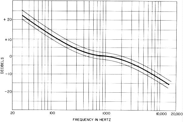
Reducing the recording lathe speed by one-half shifts the pre-equalization characteristics by one octave. To restore the final recording to the RIAA standard special equalization is required between the master tape and the disc-recording amplifier, so that when the disc is played back at its normal speed, it has the RIAA standard characteristics. To accomplish this, the following conditions must prevail:
Tape recorder equalized for NAB standard characteristic at both 7.5 and 15 ips.Although this method of recording is generally confined to 45-rpm recordings, it may be used successfully with any system if due consideration is given to the intervening equalization. Pressings made from half-speed recordings are played back at their normal speed of 33-1/3 rpm or 45 rpm. A typical equalization curve suitable for connection between the master tape machine and the disc-recording channel is given in Fig. 13-108. (See Question 17.228.)Disc-recording system equalized for RIAA recording characteristic.
Tape originally recorded at 15 ips, using standard NAB characteristic, played back at 7.5 ips.
The recording lathe is rotated at 16-2/3 rpm for recording 33-1/3 rpm masters, or 22-1/2 for 45-rpm masters, and 39.13 for 78.26 rpm.
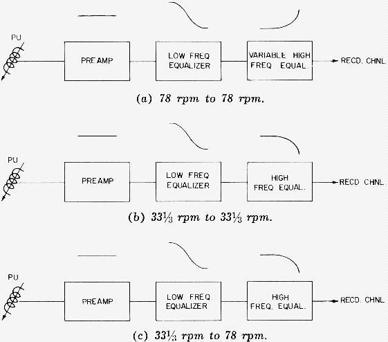
13.109 What are the methods used for recording from one characteristic to another?- They are as shown in Fig. 13-109. At (a) the pickup is shown feeding a preamplifier with a fixed low-frequency equalizer and variable high frequency equalizer at its output. This circuit may be used to rerecord one 78-rpm recording to another 78-rpm recording. The low-frequency equalizer is set for the proper low-frequency compensation and the high-frequency equalization is used to boost or attenuate the high frequencies as required. If possible, the high frequencies should be increased from 4 to 6 dB, surface noise permitting.
A 33-1/3-rpm recording being transferred to a similar type recording is shown at (b). The regular equalization used for reproducing such records is used. The recording equalization is that which is regularly used for such type recordings.
A 33-1/3-rpm recording being transferred to a 78-rpm disc is shown at (c). Again, the regular reproducing equalizers are used; however, the equalization in the recording circuits is that required for normally recording 78-rpm records.
An important point to remember is that the original recording is reproduced in a normal manner, except for a slight increase of high frequencies to compensate for transfer losses. The recording circuits are normal for the type recording being made.
| Hz | dB | Hz | dB | |
| 30 | -18.61 | 4,000 | +6.64 | |
| 50 | -16.96 | 6,000 | +9.62 | |
| 70 | -15.31 | 7,000 | +10.85 | |
| 100 | -13.11 | 8,000 | +11.91 | |
| 200 | -8.22 | 9,000 | +12.88 | |
| 300 | -5.53 | 10,000 | +13.75 | |
| 400 | -3.81 | 11,000 | +14.55 | |
| 700 | -1.23 | 12,000 | +15.28 | |
| 1,000 | 0.00* | 13,000 | +15.95 | |
| 2,000 | +2.61 | 14,000 | +16.64 | |
| 3,000 | +4.76 | 15,000 | +17.17 |
13.110 What are the actual values in decibels of equalization used for the RIAA standard reproducing characteristic?- The actual values in decibels are tabulated below and are values from which the curve of Fig. 13-95 is plotted. The recording characteristic is the inverse of this curve. The original standard specified the frequency response of the recording system, but later it was found to be more practical to specify the reproducing characteristic. (See Question 13.93.) The characteristics of this curve may be obtained by the use of three networks having 3180, 318, and 75 microseconds each.

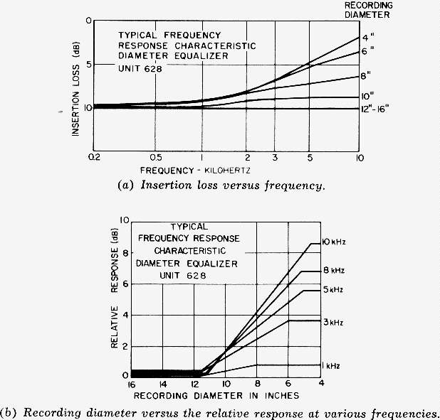
13.111 What is diameter equalization?- The use of a variable equalizer in the recording circuit to compensate for the loss of high frequencies at the smaller groove diameters caused by the decreasing groove velocity. The equalizer consists of a bridged-T network of constant insertion loss as described in Question 6.15. The shaft of the equalizer attenuator is mechanically connected to the cutting-head carriage on the recorder as shown at R in Fig. 13-2. The loss of the attenuator is controlled by the position of the cutting-head carriage relative to the diameter of the recording surface. Thus, the correct amount of equalization is inserted for a particular diameter.
Generally, for 16-inch transcriptions, the equalization begins to take effect at a diameter of 12 inches and continues in steps of 0.5 dB for a total of 6 to 8 dB to a diameter of 5 inches. The resonant frequency of the equalizer depends on the bandwidth of the recording. Diameter equalization is not practical at diameters less than 6.5 inches, as the intermodulation and tracking problems in the finished record increase quite rapidly below 7 inches.
A typical diameter equalizer-attenuator, with its mounting bracket, and control pulley, is shown in Fig. 13-111A. A spiral spring under the pulley returns the attenuator to its normal position when the recording-head carriage is returned to the outside diameters. The network elements are mounted in a nested shielded case separate from the attenuator pot. Diameter equalization should not be confused with pre- and post-equalization as they are two separate networks. Typical frequency characteristics for diameter equalization are sh@wn in Fig. 13-IIIB.
With the advent of hot-stylus recording techniques, diameter equalization is not always used. However, with cold-stylus recording it is essential. In using diameter equalization, one important factor must be borne in mind. As the high-frequency equalization is increased, so are the high-frequency distortion products. Therefore, the distortion in the amplifier system must be kept to a low value.
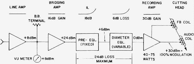
13.112 Where is a diameter equalizer connected in a recording channel?- A typical monophonic recording channel is shown in Fig. 13-112, with both pre- and diameter equalization, and the approximate operating levels. The signal from the mixer console or tape machine is applied to a line amplifier which, in turn, drives a bridging bus. From the bus, the signal goes through a bridging amplifier to a pre-equalizer having such characteristics that the playback characteristic conforms to the industry standard (Fig. 13-95).
From this equalizer, the signal passes to the diameter equalizer, which is variable, and automatically operated from a mechanical connection on the recording lathe. (See Question 13.111.) This is followed by a power amplifier of 40- to 75-watts output for driving the cutting head. Although the circuit diagram indicates a negative-feedback cutting head, the same circuitry is used with a nonfeedback head.
The approximate gain and frequency characteristic is shown above the various components. In lining up such a channel for recording, either 400 Hz or some other frequency may be used, depending on the frequency characteristics of the equalizers. Because of the characteristics of the equalizers, the exact same frequency must be used each time the channel is lined up. This is accomplished by applying, for example, 400-Hz signal to the line amplifier and setting the bus level to plus 8 dBm, and making a test cut which should measure 100-percent modulation of the cutting head.
The components shown in the diagram are not of any given manufacture or design but are only representative of typical characteristics and placement in the circuit. A complete magnetic tape transfer channel to disc is discussed in Question 17.228.
What power is recommended for the bridging amplifier shown in Fig. 13-112?- It should be capable of producing one watt or more of power to prevent the distortion from becoming excessive when the full equalization is being used.
13.114 What output power is recommended for driving a cutting head?- The minimum for satisfactory results is 40 watts; 75 is desirable, and 100 to 150 watts is not uncommon. The amplifier output should have a damping factor of at least 20, and higher if possible. The harmonic and intermodulation distortion should not exceed 1 percent at full power output.
13-115 What is the formula for calculating the playing time of a disc record?
| T= | NS rpm |
where,BR>
T is the playing time,
m= minutes,
S is the recorded width in inches,
N is the number of lines per inch, rpm is the turntable speed in revolutions per minute.

13.116 What is a stroboscopic disc?- A circular disc containing a number of black and white bars, which is used for checking the speed of turntables and other rotating machines. (See Fig. 13-116.) The disc is placed on the turntable and the bars observed under a light source fed from the normal ac lighting circuits. When the speed of the turntable is correct, the black bars will appear to stand still. If the table is turning too fast, the bars speed up and drift in the direction of rotation. When running slow, the reverse takes place, Stroboscopic bars may be painted around the rim of a turntable and a 115-volt neon light mounted close by for constant observation.
13.117 What is the formula for calculating the bars on a stroboscopic disc?
| Bars = | F x 2 x 60 rpm |
where,
F is the frequency of the light used to observe the bars,
rpm is the speed of the turntable in revolutions per minute.
The number of bars required in a stroboscopic disc using 60-Hz lighting current is:
| rpm | bars | |
| 16 | 450 | |
| 33-1/3 | 216 | |
| 45 | 159 | |
| 78.26 | 92 |
The design of stroboscopic discs for use on projectors and cameras is discussed in Question 3.87.
13.118 What is a light pattern?- A test record recorded to measure the frequency response of a disc-recording channel. Frequencies of constant amplitude are sent into the channel and recorded, using the normally employed equalizers. The finished record is then viewed under a light held parallel to the surface of the record. The pattern seen is the frequency response of the recording channel including all components and the cutting-head characteristics. The subject is further discussed in Question 23.75.
13.119 What is a Christmas tree pattern?- A light pattern similar to that described in Question 13.118.
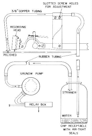
13.120 What is a vacuum system and its purpose?- A suction system used for removing the chip from a disc record as the recording head moves across the face of the disc. A typical vacuum system is shown in Fig. 13-120.
13.121 How is a recording blank held by vacuum to a recording turntable?- the vacuum system used for removing the chip from the record while recording is connected to a group of holes in the periphery of the turntable, thus holding the blank in place. (See Question 13.2.)
13.122 What does the term "cut" mean?- To stop or cut off. It is also used to designate a sound track in a disc record.
13.123 What is a copper master?- A thin sheet of copper which is electroplated onto the surface of an acetate or soft wax master disc. When removed from the master, it is a negative of the original.
13.124 What is a nickel master?- A nickel-plated copper master; also a negative.
13.125 What is silver spraying?- It is a method of metalizing the lacquer master with silver, using a dual spray nozzle, wherein ammoniated silver nitrate and a reducer are combined in an atomized spray to precipitate the metallic silver.
13.126 What is gold spluttering?- A method of gold plating a master disc record by the use of a water-cooled vacuum chamber. A metal plug is inserted in the center hole of the record and connected to a source of positive dc high voltage. A gold button connected to the negative high voltage is placed near the center of the record. The high voltage causes the molecules of the gold button to pass to the surface of the disc, depositing a layer of gold approximately one molecule in thickness on the disc. This method is used in place of electroplating. This method is now obsolete.
13.127 What is a stamper?- The metal negative of the original master used in a hydraulic press for stamping the finished record. A typical record press is shown in Fig. 13-127. Hydraulic pressure combined with heat supplied by live steam passing through the record press molds the plastic biscuit into a record. Cold water is circulated through the blocks in the press for a few moments before releasing the pressure and removing the record.
13.128 What is a matrix?- A stamper. The image is negative.
13.129 What ia a mother?- A nickel-plated positive of the original record used for making stampers.
13.130 What is a pressing?- A commercial phonograph record. It may be formed with or without heat.
13.131 What is a metal master?- A copper master. (See Question 13.123.)
13.132 What is a back plate?- A metal or wood backing to which a copper or negative master is attached to facilitate handling.
13.133 What is a master recording?- The original recording which may be a disc, film, or a magnetic tape.
13.134 What is a platen?- A flat circular plate used in the hydraulic press to hold the stamper.
13.135 What is a reverse copy?- A metal copy of the nickel master made by means of electroplating. It is an exact duplicate of the original recording. After mounting on a back plate it is called a master.
13.136 What is a shellac pressing?- A commercial record made some years ago, and so called because the compound contained shellac, which provided a hard surface; now obsolete.
13.137 What is a binder?- A substance used to bind the basic materials in a processed record together.
13.138 What is a filler?- A substance added to the basic material used in processed records to provide color and weight.
13.139 What is a biscuit?- A dough-like material used in the manufacture of phonograph records. (See Fig. 13-127.)
13.140 What is a wax record?- A recording blank made of soft wax and composed of soap, styric acid, and other ingredients. It is used for recording the original master and is processed in a manner similar to any other master. Soft wax was the original method used for making disc records; however, it is now obsolete, having been replaced by the acetate disc master.
13.141 What is vinylite?- A plastic material used in the manufacture of phonograph records because of its low surface noise and its resistance to breakage.
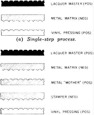
13.142 Describe the procedures for processing disc records.- Two methods may be used-the single-step and the three-step process - as illustrated in Fig. 13-142. The single-step method is used when less than 200 pressings are to be made and consists of a lacquer master, metal matrix, and a vinylite pressing. The three-step method is used where more than 200 pressings are required and the master must be reused.
13.143 What method is recommended for storing disc records?- They should be stored edgewise.

13.144 How should masters be packed for shipment?- They should be packed as shown in Fig. 13-144.
13.145 What is an air check?- A recording made from a radio broadcast by means of a radio receiver.
13.146 How should recording blanks be handled?- They should be handled by the edges only. Never permit the hands to come in contact with the recording surfaces as the oil from the fingers causes noisy spots in the processed disc.
13.147 What precautions should be taken when recording a master to be processed?- It should be visually inspected for defects in the surface before recording. After recording, it should again be inspected with a magnifying glass for breakthroughs in the walls of the sound track. A playback record cut at the same time the master was recorded is used for checking for quality and cues. Discs to be processed are never played back, as damage to the sound track may result.
13.148 Describe a compatible recording.- In the reproduction of disc records, if a stereophonic recording is played on a reproducer employing a lateral or monophonic pickup, the sound track modulations will be damaged because of the nonvertical compliance of the pickup motor mechanism. It has long been the aim of recording engineers to produce a sound track that would play equally well using either a monophonic or stereophonic pickup. Experiments seemed to indicate that it was the low-frequency vertical signal that caused most of the wear. If the low-frequency signal was removed from the vertical portion of the sound track, the low frequencies would appear in the lateral component which represents the sum of the two channels, because the vertical information represents the stereo information equal to the difference between the two channels. Recordings made in this manner show considerably less wear when reproduced using a lateral pickup. However, further study indicates that stereo information is carried by the low frequencies and leads to the degradation of the quality of reproduction.
Experience indicates that at the present time stereophonic recordings should not be played back using a monophonic pickup. However, monophonic recording can be reproduced quite satisfactorily using a stereophonic pickup.
13.149 How may acetate discs be cleaned?- With a weak solution of soap in cool water.
13.150 How may the sound-track groove depth be calculated?
For an included angle of 87 degrees:
Groovedepth = 0.5269 X A - 0.4527 X R
For an included angle of 70 degrees:
Groovedepth = 0.7141 X A - 0.7434 X R
where,
A is the groove width,
R is the stylus tip radius.
The groove width is measured with a calibrated microscope.
13.151 How much does the RIAA high-frequency pre-equalization improve the signal-to-noise ratio?- It will improve the signal-to-noise ratio by 8 dB, resulting in an effective signal-to-noise ratio of 58 dB under minimum conditions. (See Question 13.95.)
13.152 What is a negative-feedback cutting head?- This device is discussed in Section 14.
13.153 What is hot-stylus recording?- The use of a heated stylus during the recording process. This method reduces the pressure on the recording stylus and improves the high-frequency response as well as the signal-to-noise ratio. This subject is discussed in length in Questions 15.60 to 15.71.
13.154 How does turntable rumble affect low-frequency reproduction?- Turntable rumble has a high energy content and causes the cone of the loudspeaker to operate in the nonlinear portion of the speaker characteristic, distorting the low frequencies. If the rumble is great enough, the reproduction sounds as though the cone were breaking up.
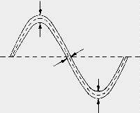
 | (a) Waveform recorded at a high groove velocity. |
| (b) Same waveform recorded at a low groove velocity. |
13.155 Show how a given waveform is affected by a change in the groove velocity.- A given waveform recorded at a diameter of 12.5 inches and at 5.5 inches is shown in Fig. 13-155. It will be noted the waveform at 5.5 inches is cramped into a space less than half that at 12.5 inches. This complicates tracking and increases the noise and distortion.
13.156 What is the minimum separation specified for stereophonic reproduction?- The separation between recorded and unrecorded channels measured at the output of the reproducer with its equalizer and preamplifier must be at least 26 dB over the range of 100 to 7500 Hz, and the separation shall not fall off at a greater rate than 6 dB per octave. As the values specified may be subject to noise and erratic measurement, it is suggested, if possible, that a tuned voltmeter be used for such measurements.
13.157 What is the standard for balance between stereophonic channels?- Playing back a record, with the output of each channel adjusted to within 0.25 dB at 100O Hz, the frequency response of each channel shall agree with the standard reproducing curve of Fig. 13-95, within plus-minus 1 dB between 100 Hz and 7500 Hz, and within plus-minus 2 dB above and below these frequencies. Equal modulation for the two sides may be obtained by using a monophonic lateral test record.
13.158 What is the standard for phasing a stereophonic recording channel?- For recording, the standard states that equal in-phase signals applied to the left and right channel inputs of a stereo disc recorder shall result in lateral modulation of the stereo groove. Conversely, equal antiphase signals produce vertical modulation. For reproducing, the lateral modulation of the groove will produce equal in-phase voltages at the output of the pickup, and, conversely, that vertical modulation will produce equal antiphase voltages. (See Question 13.202.)
13.159 How does the distortion vary for lateral recording?- It varies as the square of the signal amplitude, as the square of the stylus radius, as the square of the frequency, and, inversely as the groove velocity.
13.160 How does the distortion vary for a vertical recording?- It varies directly as the signal amplitude, directly as the frequency, directly as the stylus radius, and directly as the groove velocity.
3.161 Define groove angle.- It is the angle between the two side walls of a groove, measured in a radial plane perpendicular to the disc surface.
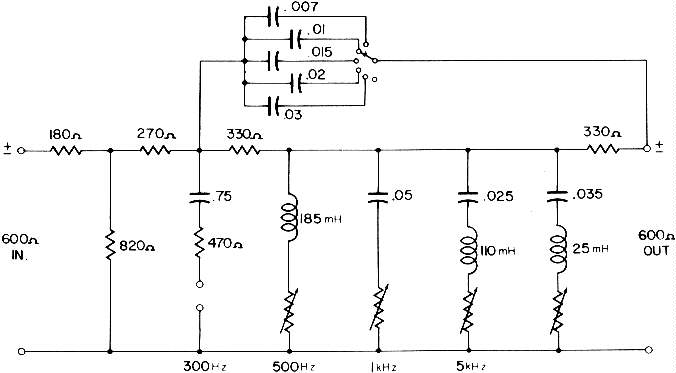
13.162 Show the schematic diagram for a cutting-head filter or preequalizer.- A recording filter or equalizer for recording, using the RIAA recording characteristic, developed by H. E. Roys of RCA is shown in Fig. 13-162A.
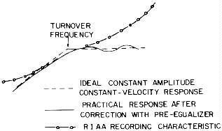
The circuit consists of an input pad, and five adjustable circuits for smoothing out the frequency response of the cutting head. An ideal cutting-head recording characteristic and a practical response curve are shown in Fig. 13-162B, with the RIAA recording characteristic. The practical response is attained by the use of the recording filter shown in Fig. 13-162A. The small peaks and valleys in the final cutting-head response are quite small and may be considered to be flat for all practical purposes. The high-frequency tilt-up of the RIAA characteristic is obtained by the adjustment of the capacitors in parallel with the upper portion of the filter network. The frequency response of the cutting head is adjusted by means of the adjustable circuits in the filter network for the smoothest frequency response by recording a series of light patterns or by the use of a cutting-head calibrator, discussed in Question 14.49. (See Question 23.75.)
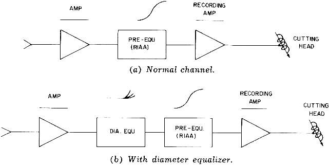
13.163 How is the recording filter of fig. 13-162 connected in the recording circuit?- The recording filter or equalizer may be connected in the recording channel in several different ways. The network is connected ahead of the recording amplifier at part (a) in Fig. 13-163A. At part (b) it is connected in tandem with a variable diameter equalizer.
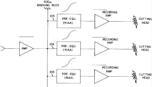
Three disc recorders driven from a bridging bus are shown in Fig. 13-163B. In this instance, the recording filters are designed with a l0,00-ohm bridging input transformer connected across a 600-ohm bus. Separate recording amplifiers are used for each recorder. In this type arrangement a diameter equalizer cannot be used.
13.164 How is 100-percent modulation of a cutting head determined?- It may be achieved by two methods: by having a VU meter connected across the head circuit or by recording an unmodulated groove and measuring its width, using a calibrated microscope. The latter method is preferred as it takes into consideration the characteristics of the disc material, stylus heat (if used), and any other factors associated with the actual displacement of the cutting-head stylus. The gain control in the recording amplifier should have 1/2-dB steps to permit accurate adjustment of the 100-percent modulation. The frequency used for lining-up the channel before recording should be at a predetermined frequency, taking into consideration the equalizer characteristics. (See Question 13.112.)
13.165 Define translation loss (playback).- It is the loss suffered in the reproduction of a pressing, whereby the amplitude of the reproducer stylus differs from the recorded amplitudes on the record.
13.166 What is the recommended reproducing characteristic for 16-inch 33-1/3 -rpm recording?- The same frequency response as for 33-1/3 -rpm microgroove recording (Fig. 13-95). As this type recording uses coarse pitch, the recording stylus uses an included angle of 88 degrees, plus-minus 5 degrees, with a tip radius of 1.5 mils.
13.167 What is the recommended reproducer characteristic for 78.26-rpm recording?- The same frequency response as for 33-1/3 -rpm microgroove recording (Fig. 13-95). Because this type recording uses a coarse pitch, the recording stylus uses an included angle of 87 degrees, with a tip radius of 1.5 mils.
13.168 What is the recommended reproducing characteristic for 16-2/3 -rpm recording?- The frequency response follows the same general characteristic as for the microgroove. However, it may require some correction to obtain a satisfactory finished product. Such records are recorded using microgroove techniques. Recordings such as these are used for books for the blind and other extremely long playing records. (See Question 13.22.)
3.169 What does the abbreviation "RIAA" mean?- It is the initials of the Record Industry Association of America. It is also used to designate the reproducing characteristic adopted by all the leading recording companies as a standard for record reproduction. It has also been adopted by many of the record manufacturers of Europe. The standard was adopted in June, 1953, and reaffirmed in March, 1964. This characteristic is discussed in Question 13.95, and the actual values of equalization in Question 13.110.
13.170 What is pinch effect?- See Question 16.27.
13.171 Define tracking error- It is the inability of the reproducing pickup stylus to properly follow the recorded groove, thus inducing distortion and noise with possible damage to the groove modulations. Trackability is now the generally accepted term, rather than tracking error. (See Questions 13.172 to 13.174, and 16.42.)
13.172 What are the most common causes of poor tracking in a reproducer?- Some of the most common causes are pinch effect, groove too shallow or too light, turntable not level, bent recording blank, overmodulation of the sound track, and side walls of the groove broken through.
3.173 What is tracing distortion?- Nonlinear distortion in reproduction of a disc record. Distortion is created because the curve traced by the playback stylus is not an exact replica of the modulated groove. Tracing distortion is caused by the stylus tip which is round and of finite radius. If the wavelengths of the modulations are of the same dimensions as the stylus tip, difficulty will be experienced when attempting to reproduce the sound track.
The effects of tracing distortion become greater as the smaller diameters are approached because of the lower groove velocities. Tracing distortion is created because the playback stylus and the cutting head stylus contact do not occur at exactly the same point. In tracing a groove, the playback stylus contacts the groove wall at a point different from that made by the recording stylus. This difference of position causes distortion in the reproduction. With the advent of the biradial or elliptical reproducing stylus, the effect of tracing distortion has been considerably reduced. (See Questions 13.30 and 13.32.)

13.174 What is tangent error?- When a laterally recorded disc record is recorded, the cutting head is carried across the face of the recording disc at right angles to the direction of the disc motion. However, when reproduced, the pickup is never at right angles to the direction of motion, except at one point, because the pickup arm is pivoted in such a manner that it swings across the face of the disc in an arc as shown in Fig. 13-174. Point A is the only place where the stylus point is at right angles to the direction of motion.
The constant change of angle by the playback stylus causes a strain on the sidewalls of the record groove, which eventually tears out the high frequency modulations, leading to increased noise and distortion. (See Question 16.52.)
13.175 Define constant-velocity recording.- Constant-velocity recording indicates a mechanical recording characteristic wherein, for a fixed amplitude sine wave, the resulting recorded amplitude is inversely proportional to frequency. 13.176 What is a sweep-frequency record?- A test record on which have been recorded a series of constant-amplitude frequencies. Each frequency is repeated 20 times per second starting at 50 Hz and continuing up to 10,000 Hz or higher.
The record is played back and its output observed by means of an oscilloscope connected at the output of the playback unit. Marker frequencies appear at intervals to identify the frequencies. The use of these records is discussed in Question 23.141.
13.177 What is the nomenclature for recording and reproducer styli?- This subject is discussed in Section 15.
13.178 What are the included angles used with recording and reproducing styli?- This information is given in Section 15.
13.179 What are the characteristics of a magnetic cutting head?- This subject is discussed in Section 14.
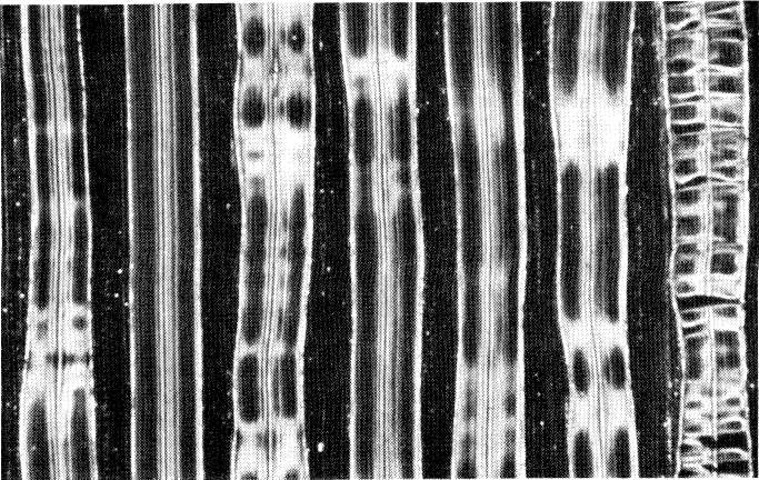

13.180 What are the standard groove characteristics for stereophonic recordings?- The plane of modulation in a 45/45-degree stereophonic disc groove shall have orthogonal modulation planes inclined at 45 degrees to a radial line on the surface of the disc and at the intersection of the modulation planes and be normal to the radial lines. The outer wall of the groove shall contain the right-hand channel information and the inner wall the left-hand information. The phase relationship between channels shall be such as to result in lateral groove displacement when the stereo-recording system is driven with equal amplitude and in-phase signals, and the groove displacement shall be vertica when the recording system is driven by equal amplitude signals in antiphase or 180 degrees. (See Figs. 13-180A and B, and Question 13.104.)
13.181 What is the standard groove shape for stereophonic pressings?- The groove shape shall have an included angle of 90 degrees, plus-minus 2 degrees, with a top width of not less than 0.001 inch, and a bottom radius not greater than 0.002 inch. For these groove dimensions it is recommended the reproducing stylus have a tip radius of 0.0005 to 0.0007 inch, with an included angle of 40 to 45 degrees.
It will be noted that the groove dimensions mentioned above apply to the finished product rather than to the recording stylus. In some instances, the groove dimensions may depart slightly from those of the recording stylus; however, these variations can generally be controlled in the processing plant. In the event that it is necessary to play back both monophonic and stereophonic discs with the same reproducer, the use of a 0.007-inch stylus is desirable.
13.182 What is the lines-per-inch rate for starting spirals?- Eight grooves per inch, plus or minus 2.
13.183 How many grooves are recommended before the first modulation occurs?- Not less than two nor more than four complete revolutions.
13.184 What are the smallest recommended diameters to be recorded?-
| For 16-inch transcriptions at 33-1/3 rpm using a reproducing stylus of 2.3 mils | 7.5 inches. |
| For 78.26-rpm recordings | 3-3/4 inches. |
| For 45-rpm recordings | 4-1/4 inches. |
| For 33-1/3 rpm microgroove recordings | 4-3/4 inches. |
13.185 What is the standard for run-in grooves and the smallest groove on the inside?- there shall be at least one unmodulated groove at the recording pitch before the recording, and one at the end of the recording. The last modulated groove shall not be less than 4-3/4 inches in diameter for 33-1/3 rpm discs, and 4-1/4 inches for 45-rpm discs.
13.186 What is the standard for concentricity of the center hole?- It shall be concentric with the recorded groove spiral within 0.005 inch, with a diameter of 0.286 inch plus 0.001 inch, minus 0.002 inch for 33-1/3 rpm recording. For 45-rpm discs, the hole is 1.504 inches, plus-minus 0.002 inch. Warping of the disc shall not exceed a total indicator reading of the surface in excess of 1/16 inch, within any 45-degree segment, with a total reading of the indicator not to exceed 1/32 inch.
13.187 What is the recommended groove width for coarse-pitch recording?- For lateral recordings the finished groove should have an included angle of 88 degrees, plus or minus 5 degrees, for a top width of not less than 4.0 mils for records to be reproduced with a stylus having a tip radius of 2.3 mils.
13.188 What is the average dynamic range of a disc recording?- For high quality recordings, the dynamic range is:
| Shellac pressings, lateral cut | 32 to 40 dB |
| Microgroove vinylite | 40 to 55 dB |
| Vertical cut | 40 to 45dB |
| Special systems microgroove | 45 to 60 dB |
| 16-inch coarse-pitch, lateral cut | 45 to 60 dB |
13.189 What is the recommended groove width for vertical recordings?- For an included angle of 88 degrees, plus or minus 5 degrees, the bottom radius should be 2.0 to 2.3 mils, with a top width of not less than 4.0 mils.
13.190 What is grouping?- Uneven spacing of the grooves. The grooves should be so spaced that at no one point does the pitch deviate from the mean by more than 5 percent for constant-groove space recording.
13.191 What is flash?- It is the excess compound generated at the edge of a pressing, during the compression moulding of a disc record. The edge is later buffed smooth.
13.192 What is the procedure for recording standard test records?- Standard procedures for this type recording have been set forth in the National Association of Broadcasters (NAB) Standard, "Disc Recording and Reproduction," March, 1964.
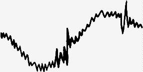
13.193 What is modulation noise?- Noise created by the signal. The signal is not included as a part of the noise. A typical modulation noise pattern is shown in Fig. 13-193. With the use of hot-stylus techniques, modulation noise has ceased to be a problem.
13.194 What is a poid?- The curve traced by the center of a sphere when it rolls or slides over a surface having a sinusoidal profile. It is the path traced by the reproducer stylus of a vertical pickup.
13.195 What is shaving a record?- In the days when soft wax was used for recording masters, the recording blank was rotated at a high speed and a thin shaving was removed from the surface to obtain a high polish.
13.196 How does tracing distortion differ in a vertical recording?- When a sine wave is reproduced from a vertical recording, the curve traced by the stylus tip is a poid. (See Questions 13.173 and 13.194)
13.197 What is the transition frequency?- It is the frequency where the recording characteristic departs from constant velocity to one of constant amplitude. It is also called the crossover or turnover frequency. (See question 14.8)
13.198 Define the term "off-set angle."- In lateral-disc reproduction, the off-set angle is the smaller of the two angles between the projections into the plane of the disc of the vibration axis of the pickup stylus and the line connecting the vertical pivot (assuming a horizontal disc) of the pickup arm with the stylus point. (See Questions 13.30, 13.32, and 16.60.)
13.199 Describe a typical pickup and reproducing system test record.- Several different test records are available for making individual tests on pickup and for testing complete reproducing systems. Records for the testing of pickup characteristics include frequency response measurements with frequency announcements from 20 to 20,000 Hz, separation tests (crosstalk), pickup-arm resonance, stylus wear wavelength loss, and compliance and phasing. A standard reference level is also included (7 cm per second). Other records for the measurement of harmonic and intermodulation distortion are also available.
Records designed for complete system testing generally include identification of left and right channels, stereo balance, loudspeaker phasing, rumble test, stylus wear, pickup-arm resonance flutter, RIAA frequency-response section, and a standard reference level. (See Question 13.192.)
13.200 What is side thrust?- The radial component of force on a pickup arm caused by stylus drag.
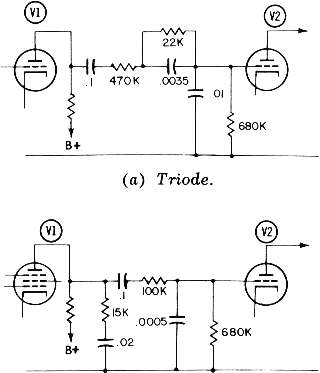
13.201 Show an RC equalizer circuit suitable for reproducing the RIAA reproducing characteristic.- Two such circuits are shown in Fig. 13-201. Solid-state circuits are given in Section 12.
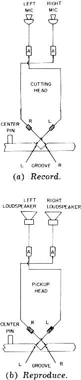
13.202 Show the relationship between the coils of a stereophonic cutting head and those of a pickup.- Referring to Fig. 13-202, the connections for the cutting head coils are shown at part (a) and those of the pickup are shown at part (b). Because of the mechanical design of the cutting head, the left- and right-hand sides of the program material are reproduced by the coils on the opposite sides of the record groove.
When the program material is recorded, as shown at part(a) , the lefthand side is recorded on the left, or on the inside wall of the groove. The right-hand side of the program material is recorded on the right, or outside of the groove.
When the record is reproduced, the right-hand pickup coil is connected to the left-hand amplifier and loudspeaker. The left-hand pickup coil is connected to the right-hand amplifier and loudspeaker. This procedure is necessary because of the mechanical design of the pickup.
The RIAA standard for stereophonic reproduction is that when two identical signals are fed to the cutting head actuating the coils in-phase, only a lateral sound track is recorded. Conversely, equal antiphase signals will produce only vertical modulations. It is assumed that the reproducing system after leaving the pickup is properly phased. (See Question 13.158.)
13.203 What are the general characteristics of an embossed sound track?- In an embossed sound track the material is not removed from the disc but is pushed aside, creating tiny horns at the upper edges of the sound track. The frequency response of an embossed sound track is rather limited and generally falls between 70 and 5500 Hz. The signal-to-noise ratio will vary with different types of recording materials.
The harmonic and intermodulation distortion is affected by the material of the record, the amplitude of the signal, and an effect known as cusping in the sound track. A fairly good average of distortion is 6 to 10 percent at 400 Hz when recording and reproducing on the same machine. Crystal or magnetic cutting heads may be used; however, the crystal is preferred as it may be coupled to the recording amplifier to produce a constant-amplitude recording characteristic. The output stage should have at least 12 dB of negative feedback. (See Question 13.32.)
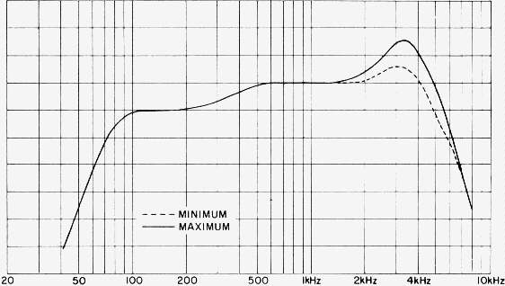
13.204 What is the frequency characteristic for an embossing recorder amplifier?- It is as shown in Fig. 13-204. It will be noted the upper midrange frequencies have been pre-equalized to obtain a greater signal-to-noise ratio and to add presence to the reproduction. The amount of pre-equalization will vary with the recording media, stylus, and cutting head.
13.205 Can embossed records be played back from the recorder using the some head and stylus?- Yes, but with a loss of signal-to-noise ratio. Using the same stylus has the disadvantage that the same included angle is used to reproduce as that used to record. This permits the stylus to ride in the bottom of the groove increasing the noise in the reproduction. The signal-to-noise ratio for this type operation is about 20dB. Playing the same record back using a greater tip radius will increase the signal-to-noise ratio 10 dB.
13.206 What is the relationship of a constant-groove velocity to recording time?- The recording time is proportional to the area of the recording. Since the area of a circle is proportional to the square of its radius, it becomes possible to record long periods of playing time using 300 lines per inch.
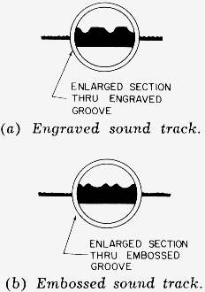
13.207 Show a cross-sectional view of an engraved and an embossed sound track.- A cross-sectional view of an engraved sound track is shown at part (A), and an embossed sound track is shown at part (b) in Fig. 13-207. In the engraved sound track the material is removed from the disc as the recording progresses. In the embossed sound track the material of the disc is displaced and shoved upward, appearing as two small ridges at the edges of the sound track.
13.208 What is the average pressure developed in an embossing system of recording?- About 20,000 pounds per square inch. To reduce the friction, the recording blank is impregnated with a lubricant and the surface treated with wax.
13.209 What type medium is recommended for embossed sound tracks?- As a rule, cellulose acetate about 0.15 inch in thickness is used; however, in some instances vinylite is used.

13.210 What is acoustic recording?- The original method of recording by causing the sound waves to actuate a diaphragm to which is attached a stylus. The stylus bears on the recording medium and mechanically engraves a sound track corresponding to the impressed sound waves. This is the method used before the advent of electrical recording. Acoustic recording is also called mechanical recording.
Because the output of most of the instruments used for recording is low and a considerable amount of energy is required to obtain a satisfactory level on the record, horns were attached to the string instruments to reinforce their acoustic output. A typical recording session in the early 1920s is pictured in Fig. 13-210.
The sound mixer consisted of a ball of yarn in a tube attached to the large horn at the left. The position of the ball of yarn in the tube was varied to regulate the volume of sound fed to the recording diaphragm and stylus.
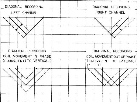
13.211 Describe the geometry of a 45/45-degree stereophonic record groove cut with a 90-degree included angle stylus.- A cross-sectional view of a 45/45-degree record groove for four limiting conditions is shown in Fig. 13-211. A recording stylus with an included angle of 90 degrees is used.
The plot at the upper left illustrates the type of groove that will be recorded when the signal is fed to the left-hand channel only. The right-hand wall of the groove will be a slant line varying in depth. The right-hand edge will be smooth and without modulation. The left edge of the groove will be varied in accordance with the signal.
The plot at the upper right of the diagram depicts the reverse condition when the signal is fed to the right-hand channel only. The plot at the lower left of the diagram shows the type of groove recorded when two identical signals in phase are fed to the two cutting-head driving coils. For this condition, a vertical recording results.
The plot at the lower right shows the groove recorded when the two signals are out of phase at the driving coils. For such a condition, a lateral recording will result. During an actual stereophonic recording session, all four of the described conditions are taking place under very complex conditions of the stylus motion.
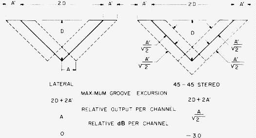
13.212 Compare a monophonic groove to that of a 45/45-degree stereophonic groove, showing the maximum permissible groove excursion.- This comparison is shown in Fig. 13-212 for the conventional lateral recorded disc and for the lateral motion in a stereophonically recorded disc. The maximum excursion for either type of groove is:
The maximum amount of lines recommended for stereophonic recording by the 45/45-degree method is 225 lines per inch, with a minimum groove width of 1 mil and a maximum bottom radius of 0.2 mil.

13.213 What are the limiting factors relative to the maximum modulation that can be applied to a 45/45-degree groove?- Refer to the cross-sectional view of a 45/45-degree stereophonically recorded groove in Fig. 13-213. The specified minimum depth is shown at D, and the maximum modulation for either cutting-head coil is indicated at A. For these conditions, the maximum horizontal excursion will be:
It should be taken into consideration that these measurements include the distortion contributed by the test oscillator, recording amplifiers, cutting head and cutting-head stylus angle, and the disc record. On the reproducing side, measurements include the distortion of the disc record, pickup, preamplifiers, and any distortion induced by equalization in either the recording or reproduction circuitry. Considering the many factors involved in disc recording and reproduction, this is not a high figure of distortion. No doubt the greatest distortion factor is the angle of the stylus to the surface of the disc. (see Question 13-30.)
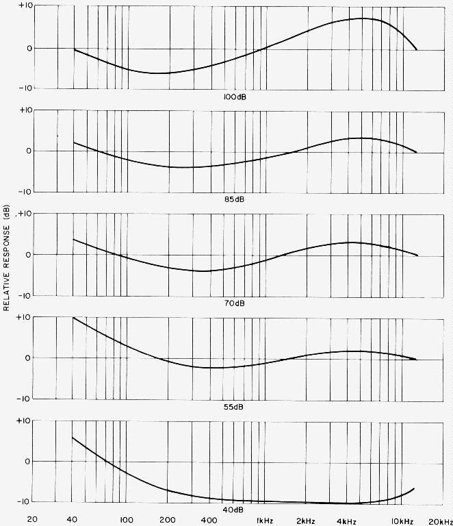
13.215 Describe the RCA dynagroove stereophonic disc record- The dynagroove system developed by RCA Victor is a combination of many factors. It is a correlation between the artist and engineer to achieve a record that will more nearly approach concert-hall reproduction in the average home by the use of several devices in the recording system. It has been found by extensive measurements that 90 percent of the consumers listen to record reproduction in their homes at a peak level of 7O to 90 dB, with the average about 80 dB. The peak level of a full symphony orchestra is about 100 dB. Thus, it may be seen that the peak level in the home is considerably lower than the concert hall. The principal reason for this lower level is that the tolerable peak level in a small room is lower than that of a concert hall, due to the shorter path of travel and the faster growth in the smaller enclosure; hence, a lower peak level of listening. Six factors enter into the realistic reproduction of sound in the home; the peak sound level, loudness versus the loudness level, frequency response of the human ear, and the reverberation characteristics of the enclosure.
When recording the original master tape in the studio, several factors are taken into consideration, such as the studio acoustics, microphone placement and directivity, frequency response, distortion of the amplifier system, and the record speed and the signal-to-noise ratio. It has been found that operating the recorder at 30 inches per second, the random signal-to-noise ratio is increased 10 dB, with a reduction in flutter and wow of 50 percent, as compared to a speed of 15 ips.
After the original magnetic tape is recorded, it is transferred to a submaster tape using a Dynamic Spectrum Equalizer to correct for differences in the listening conditions and to that of an average dwelling. The design of this equalizer is such that its frequency response is altered continuously as the program is recorded, and is a function of the program amplitude and differences in the types of musical combinations and selections. Typical frequency response curves for this equalizer are shown in Fig. 13-215.
When the level is low, the low frequencies are accentuated, At medium levels, only a slight amount of accentuation is used in the low frequencies and in the presence range (2000 to 6000 Hz), with a reduction in the response in the region between 400 and 1000 Hz. At high sound levels, the presence region is accentuated and the range below 1000 Hz is reduced. The whole object is to increase or decrease the sound level in the appropriate frequency bands so the program material may be appreciated under the existing ambient noise level and acoustic environment. Properly handled, the dynamic range is not disturbed and reproduction in a small room enhanced.
In the recording of both the master tape and the submaster, they are carefully monitored using peak-indicating volume-indicator meters. After the submaster tape has been recorded, it is transferred to a master disc, using devices termed, as "Dynamic Styli Correlators," in the left and right channels. This device corrects for the discrepancies between the angle of the recorder and reproducer stylus used by the consumer and reduces the tracking distortion at the smaller diameters by a factor of 6:1.
In addition to the factors mentioned, certain changes have been made in the record-processing procedure to improve the groove produced by the stamper and an ingredient introduced into the vinylite to reduce the attraction of dust, thus increasing the signal-to-noise ratio of the disc to 65 dB. Details of this system are given in the literature.

13.216 Describe a monophonic and stereophonic magnetic tape or film to disc transfer channel.- Pictured in Fig. 13-216A is a Westrex magnetic tape- or film-transfer channel for monophonic or stereophonic disc mastering. The channel shown is complete except for the monitor speakers, disc recording lathe, magnetic tape or film reproducer, playback turntable, and pickup.
Two cabinet-type racks house two RA-670 amplifiers, two RA-1574D 75- watt recording amplifiers, gain controls, two 40-watt monitor amplifiers, VU meters, program equalizers, variable high- and low-pass filters, patch panel, power supplies for the recording amplifiers, and preamplifiers for playback purposes.

Referring to the block diagram Fig. 13-216B, at the upper left the input signals from the left and right channels are applied to the input of two RA-670 limiter amplifiers. These amplifiers have extremely fast attack time (50-microseconds) and a variable release time. Leaving the limiter, the signals pass through high- and low-pass filters, then to the variable program equalizers. At the output of the equalizers is a gain control for balancing the gain of each channel and a two-gang attenuator for adjusting the gain of the two sides simultaneously.
The signals are now applied to a monitor switching panel where the monitoring may be taken from one of several different points in the system- the left or right cutting-head circuits, the recording channel immediately preceding the recording amplifier, the tape reproducer, or the phono jack. Two line amplifiers feed through a record on-off panel and then to two RA-1574D power amplifiers, which drive a Westrex 3-D cutting head on the recording lathe.
At the lower portion of the diagram are shown the 40-watt monitor amplifiers, preceded by a two-gang gain control and two repeat coils. At the lower left is a stereo preamplifier for playback purposes, and pickup.

Referring to the schematic diagram in Fig. 13-216C, the RA-1574D , StereoDisc recording amplifier, the incoming signal is fed to a 600-ohm impedance input transformer Tl which drives a cathode follower VIA that functions as a constant-voltage generator for the plug-in equalizer. The output from this unit is amplified by V2A and B and has a low-frequency boost for the RIAA recording characteristic. (See Question 17.162.) The signal from V2B drives V3B, then phase-inverter V3A which in turn drives power stages V4A, V4B, V5, and V6. The output transformer T2 secondary is designed for a load of 5 to 10 ohms.
A negative-feedback circuit is returned from the feedback coil in the cutting head to potentiometer Pl in the control grid of tube V7B at the lower left. The feedback signal is amplified by tubes V7B, V7A, and VIB. The output signal from VIB injects feedback voltage into the cathode of V3B and provides a high-level signal to pin A of the monitor-amplifier equalizer C-98461 at the lower center of the diagram, The signal at the output of the equalizer drives tubes V8B and V8A feeding output transformer T3, which provides a 600-ohm output at a level of plus 4 dBm, for feeding the monitor power amplifier and speaker, The plus 4 dBm develops for a peak velocity of 3.54 cm/sec recording level at the cutting head stylus tip. Tubes V9 and VIO are employed for voltage regulation for the screens of V5 and V6.
The circuitry for the equalizers is given in Figs. 13-216G and H. The Westrex 3-D cutting head is discussed in detail in Question 14.2.

Two power supplies are required, one for each amplifier. The power supply is unregulated, regulation being supplied by the circuitry in the RA-1574D amplifiers. Referring to the schematic diagram in Fig. 13-216D, the power transformer Tl has three primary taps for line voltages of 105 to 120 volts. Fullwave high voltage is obtained through rectifiers CR4 and CR5, consisting of two units in parallel, feeding a choke input filter LI. Negative-bias voltage is generated by rectifier CRI and is adjusted by control PI. The normal voltage is around 38 volts. The dc heater voltage is obtained from rectifiers CR2A and CR2B operating as voltage doublers. The output voltage is adjusted by control RI. Pilot-light voltage is supplied from the same winding. Transformer T2 provides isolation and heater voltage for regulator tube V9. A delay of 50 seconds in applying the 600 volts dc to the amplifier is obtained by the use of a delay unit VS3. Interconnections between the RA-1574D amplifier and power supply are shown at the lower left of the diagram.
Since the monitoring signal is taken from the negative-feedback circuits in the cutting head, a network (C-98461) is required having an invererse frequency characteristic to the RIAA characteristic (Fig. 13-216H). This creates the proper listening response. Equalizer C-98451 is connected between tubes VIA and V2A to supplant the negative feedback loop characteristics and provide an RIAA recording characteristic from 30 to 1000 Hz, and then constant-velocity from 1000 to 15,000 Hz (Fig. 13-216G). The insertion loss for this network is approximately 18 dB.
The statistics for the RA-1574D amplifiers are: Input impedance 600-ohms. Cutting head output 10 ohms for driving coils, and 11 ohms for negative-feedback coils. Sensitivity 14 dBm for 3.54 cm/sec peak recording velocity at 1000 Hz for both channels. Adjustable feedback up to 29 dB. Power output 75 watts continuous for 1 percent THD. Output noise 3 millivolts across 10 ohms. Monitor output level for a peak velocity of 3.54 cm/sec is plus 4 dBm.

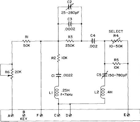

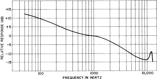
13.217 Describe the difference between lateral-vertical and 45/45-degree stereophonic recording system.- The basic principles of 45/45-degree recording heads have been discussed in Questions 13.211 to 13.213 and will not be repeated here. Both of the above methods of recording stereophonic sound cut identical grooves. In the 45/45-degree system, the driving coils of the cutting head exert their forces at an angle of 45 degrees with respect to the recording disc surface. In the lateral-vertical method, a matrixing network composed of two transformers employing double secondaries convert the left and right channel information into sum of vectors for each channel lateral and vertical. The resulting signal then becomes identical with the 45/45-degree system of recording.
The principal difference, in the two systems is the initial alignment of the left and right sides. Separation in the 45/45-degree system is fixed and depends on the mechanical construction of the cutting head. In the lateral-vertical system, this parameter is a function of balance of gain between the two sides of the system. Because the gain is fixed by the matrixing network, an absolute balance is not possible.
Since a lateral-vertical recording depends on two vector forces produced simultaneously by the lateral and vertical sides, varying the gain of one channel results in a changing of the resulting driving forces, thus reducing cross-talk ratio between the two sides. Also, if the two sides are not of identical frequency response, the effect is that of a change in gain in one side. Because of the above disadvantages, the 45/45-degree method of recording has been adopted by most recording organizations.
Recording heads manufactured by Holtzer, Westrex, Neumann, and Ortofon are the 45/45-degree variety, while those of Fairchild employ the lateral vertical design.
The lateral-vertical system is aligned initially by adjusting the amplifier gain of each side at 1000 Hz for maximum channel separation, then again adjusted for a uniform frequency response and separation simultaneously.
13.4 Dickson, Antonia and W.K.L. "Edison's Invention of the Kineto-Phonograph," Audio, Feb. 1966.
13.53 Jackson, Jolm E. "An Improved Disc for Master Recording," Journal Of the AES, April 1965.
13.80 Woodward, J. G., and E. C. Fox, "A Study of Program-Level Overloading in Phonograph Recording," Journal Of the AES, Jan. 1963.
13.88 Shiga, Takeo. "Deformation Distortion in Disc Records," Journal Of the AES, July 1966.
13.149 Wilson, Percy. "Record Contamination: Causes and Cure," Journal Of the AES,, April 1965.
13.171, 13-173 Cooper, Duane H. "On the Interaction Between Tracing and Bandwidth Limitation," Journal Of the AES,, Jan. 1969.
Lewis, W. D., and V. F. Hunt. "The Theory of Tracing Distortion in Sound Reproduction from Phonograph Records," Journal Of the ASA,, Jan. 1941.
13.217 Olson, Dr. Harry F. "The RCA Victor Dynagroove System," Journal Of the AES,, April 1964. -- "Stereophonic Sound Reproduction in the Home," Journal Of the AES,, April 1958.
Hoth, D. F. "Room Noise Spectra at the Subscribers Telephone Locations," Journal Of the ASA, Vol. 12 p 499, 1941.
Loclmer, J. P. A., and J. F. Burger. "Pure Loudness Relations," Journal Of the ASA,, Vol. 34 p 576, 1962
Books
Frayne, John G., and Halley Wolfe, Elements Of Sound Recording. New York: Jolm Wiley Sons, Inc., 1949.